As Nesteknik, our mission is to develop sustainable and efficient technologies with innovative engineering solutions.
Contact Us Nesteknik Kimya San. ve Tic. Ltd. Şti.Measuring Capability: Flow rate, total flow and temperature
Basic Styles
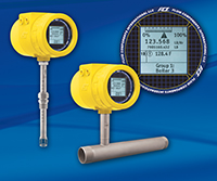
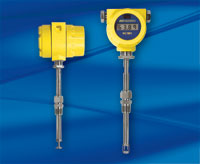
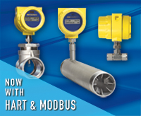
ST80: Insertion, single-point (for pipe diameters > 2 inches [51 mm])
ST80L: In-line (spool piece), single-point (for pipe diameters 1 inch to 2 inches [25 mm to 51 mm])
Flow Measurement Range
Insertion Style: 0.25 SFPS to 1000 SFPS [0,07 NMPS to 305 NMPS]
ST80L In-line: 0.0062 SCFM to 838 SCFM [0,01 Nm3/h to 1425 Nm3/h]
Air at standard conditions; 70°F psia and 14.7 psia [0°C and 1,01325 bar (a)]
Temperature Measurement Range
Up to 850°F [454°C] commensurate with element; see Operating Temperature in Flow Element specification
Media: all gases that are compatible with the flow element materials
Accuracy:
Flow: ± 1.0% reading, ± 0.5% full scale
Temperature: ±2 °F [± 1.1°C] (display only, flow rate must be greater than 5 AFPS [1,5 m/sec])
Temperature Coefficient
With optional temperature compensation; valid from 10% to 100% of full scale calibration
Flow: Maximum ± 0.015% of reading / °F up to 850°F [± 0.03% of reading / °C up to 454°C]
Repeatability
Flow: ± 0.5% reading
Temperature: ±1 °F [±1°C] (flow rate must be greater than 5 AFPS [1,5 NMPS])
Response Time (Flow): 1 sec. to 63% of final value (1 step change) typical with -FP or -FPC type flow element operating in AST™ mode
Turndown Ratio
Normally factory set and field adjustable from 2:1 to 100:1 within calibrated flow range.
Temperature Compensation
Standard: ± 30°F [± 16°C]
Optional: ± 100°F [± 55°C]
Calibration: Performed on flow stands using equipment traceable to NIST and ISO/IEC 17025
Agency Approvals:
| FM/FMc: | Class I, Division 1, Explosion proof, Groups B,C,D Class II/III, Division 1, Dust ignition proof, Groups E,F,G Class I, Division 2, Nonincendive, Groups A,B,C,D Class II, Division 2, Nonincendive, Groups E,F,G Class III, Division 1,2, Dust ignition proof, indoor/outdoor Hazardous (Classified) locations Type 4x/IP67 (per NEC 500) |
| ATEX: | II 2 G Ex db IIC T6...T1 Gb Ta= -40°C TO 65°C, IP66/67 II 2 D Ex tb IIIC T85°C...T450°C Db Ta= -40°C TO 60°C, IP66/67* |
| IECEx: | Ex db IIC T6...T1 Gb Ta= -40°C TO 65°C, IP66/67 Ex tb IIIC T85°C...T450°C Db Ta= -40°C TO 60°C, IP66/67* |
| Other: | UKEX, EAC/TR CU, NEPSI, EMSA EQM-Ex, CE Mark, UKCA, CPA, CRN, Pressure Directive 032/2013 (Model ST80L) Complies with Canadian Electrical code requirements of ANSI / ISA 12.27.01-2011 as a single seal device |
* Available in standard and elevated T-ratings
| * T-Rating (Probes) | Process Temperature Range | |
| Standard | Optional Elevated** | |
| T4/T135°C | -40°C to +65°C | -40°C to +89°C |
| T3/T200°C | -40°C to +115°C | -40°C to +154°C |
| T2/T300°C | -40°C to +177°C | -40°C to +254°C |
| T1/T450°C | -40°C to +365°C | -40°C to +404°C |
** With elevated T-rating, instruments will be fixed in AST measuring mode, not field changeable into CP mode.
SIL/IEC 61508: SIL 1 compliant, SFF 71.1% to 79.1%
Other: Follows best practices and guidelines as set forth in ISO 14511; Complies with ISO 14164
Flow Element
Material of Construction
All-welded 316L stainless steel; optional Hastelloy-C276
Operating Pressure
Model ST80 (Insertion style)
Metal ferrule: 1000 psig [70 bar (g)]
Teflon ferrule: 150 psig [10 bar (g)] (200°F [93°C] maximum)
Fixed Connection NPT: 1000 psig [70 bar (g)]
Fixed Connection Flanged: per flange rating
Model ST80L (inline style): 1000 psig [70 bar (g)]
Operating Temperature (Process)
Model ST80 (Insertion style)
Flow Elements (– FPC, – FP and – S):
-40°F to 350°F [-40°C to 177°C]
-40°F to 500°F [-40°C to 260°C]
-40°F to 850°F [-40°C to 454°C]
Wet gas/rain flow element: -40°F to 350°F [-40°C to 177°C]
Model ST80L (In-line Style): -40°F to 257°F [-40°C to 125°C]
Process Connections:
Compression Fittings Model ST80
3/4" or 1" MNPT, stainless steel with adjustable Teflon ferrule or metal ferrule; or flanged tapped and threaded for 3/4" fitting, ANSI or DIN flanges.
Compression fittings not available with 850°F [454°C] temperature versions.
Retractable Packing Glands
Low pressure 50 psig [3,5 bar (g)] or medium pressure 500 psig [34 bar (g)] with graphite or Teflon packing material; 1 1/4" MNPT or ANSI or DIN flange
Teflon packing required when process media is ozone, chlorine or bromine.
Remote configuration required with medium pressure packing gland.
Fixed Fittings / All Welded
1" male NPT or ANSI or DIN flange
Insertion Length:
Field adjustable lengths: (probe is etched with depth ruler in both inches and mm)
1" to 6" [25 mm to 152 mm]
1" to 12" [25 mm to 305 mm]
1" to 21" [25 mm to 533 mm]
1" to 36" [25 mm to 914 mm]
1" to 60" [25 mm to 1524 mm]
Fixed lengths: from 2.6" to 60" [66 mm to 1524 mm]
Model ST80L In-line Flow Tube
Flow element is threaded and keyed in an in-line flow tube, calibrated and supplied as a spool-piece; options include low flow injection tubes and built-in Vortab flow conditioners for optimum low flow rangeability and performance
Size: 1" diameter tubing; 1", 1 1/2" or 2" schedule 40 pipe; 1" schedule 80 pipe
Length: 9 nominal diameters
Process Connections: Female NPT, MNPT, ANSI or DIN flanges, or butt weld prepared
Option: Flanges sized for flow tube
Remote Transmitter Configurations:
Transmitter may be mounted remotely from flow element using interconnecting cable (up to 1000' [300 m])
Flow Transmitter
Operating Temperature
-40°F to 150°F [-40°C to 65°C]
Input Power:
AC: 85 Vac to 265 Vac, 50 Hz to 60 Hz; 10 watt maximum
DC: 24 Vdc ± 20%; 9 watt maximum
Outputs (Standard, Included)
Analog: Two (2) 4-20 mA* user assignable to flow rate or temperature. Outputs are user programmable to full flow range or subsets of full flow range.
* Outputs are isolated and have fault indication per NAMUR NE43 guidelines, user selectable for high (>21.0 mA) or low (<3.6 mA)
Digital:
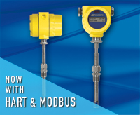
Standard: HART (v7 compliant), Modbus RS-485 and USB Serial I/O.
Optional: (Can be added to above) Foundation Fieldbus H1, PROFIBUS-PA, or PROFIBUS-DP
(Note: Only one bus comm, HART, Modbus, Fieldbus or PROFIBUS can be active at same time)
Enclosures:
Main Transmitter / Electronics:
NEMA 4X, IP66/67; polyester powder coated, ≤0.4% CU, low/no copper content* aluminum or optional in stainless steel; 4 conduit ports threaded as 1/2" NPT or M20x1.5; 7.74" x 5.40 " x 5.00" [196,6 mm x 137,2 mm x 127 mm]. (*standard effective April 2023)
Local Enclosure (Remote Configuration):
Model ST80 without packing gland option and Model ST80L
NEMA 4X, IP67; polyester powder coated aluminum or stainless steel; 2 conduit ports threaded as 1/2" NPT or M20x1.5; 3.75" x 4.00" x 3.24" [95 mm x 102 mm x 82 mm]
Models ST80 with packing gland option:
NEMA 4X, IP67; polyester powder coated aluminum or stainless steel; 1 conduit port threaded as 1" NPT or M20x1.5; 5.40" x 4.82" [137.2 mm x 122 mm]
Readout/Display (Optional):
Large 2" x 2" [50 mm x 50 mm] LCD; digital plus bar graph and engineering units
Digital displays of flow rate, total flow, temperature and pressure (with STP models); user selectable for engineering units
Analog bar graph of flow rate
Alarm status indication
User programmable 20 alphanumeric character field associated with each calibration group
Set-Up & Service mode displays text and service codes
Backlighted
Display is electronically rotatable in 90° increments to optimize viewing angle
Touch Button/Keypad (Optional)
Four (4) optical touch buttons
For user programming of instrument set-up and service interrogation
Activation through front window – no need to open enclosure to access or activate
Set and adjust the meter or interrogate diagnostics in-situ, even in Hazardous Ex (Div.1/Zone1) installation.
Note: If readout/display with buttons not ordered, all user set-up and service diagnostics interrogation must be done via computer link to bus comm and/or USB port.